Degree Objectives
What Are Degree Objectives?
Degree Objectives are UAT’s graduation requirements. Each degree has six unique objectives that qualify a student as completing a degree program in full. Each objective is home to two or more projects that fulfill the objective’s description. Furthermore, degree objectives are a way to expand on specialized projects to demonstrate understanding. Since I am completing two separate degrees, Digital Maker & Fabrication and Robotics & Embedded Systems, I am fulfilling twelve different objectives with multiple projects. Read more about each of my individual projects below!

View the Degree Objectives Explanation Videos Below!
DMF Degree Objectives Video
RES Degree Objectives Video
Digital Maker & Fabrication Objectives
1. Demonstrate the ability to prototype, build and apply for patents for technology products meeting specific human factors, form and function criteria.
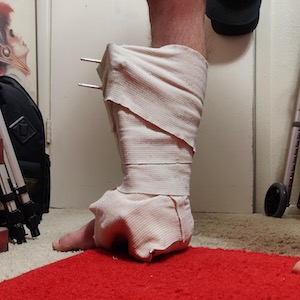 Picture of Broken Leg
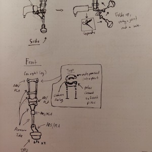 Design Drafting of Device
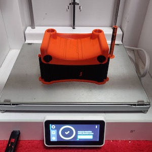 3D Printed Components
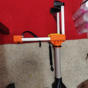 Final Product
Description
I was inspired to complete this project due to my motorcycle accident in February of 2020 which resulted in my leg being broken and in a cast for many months. Not wanting to use a walker anymore, I designed, fabricated, and assembled a crutch device that attached to my leg and would redistribute the weight through my knee instead of my lower leg, allowing me to walk normally. I utilized SolidWorks for the digital design of components, an Ultimaker S5 3D Printer for fabrication, and PLA, TPU, and PVC as the materials of choice.
Objective Application
This project applies to Objective 1 of the DMF degree by designing and prototyping a device that had to meet specific human factors and be functional for a person that could not put weight on a broken leg. The device had to meet form and function criteria; being robust enough to support a person’s weight while not being heavy or large.
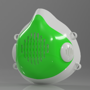 MaxMask Front
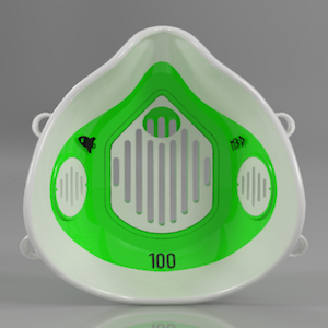 MaxMask Back
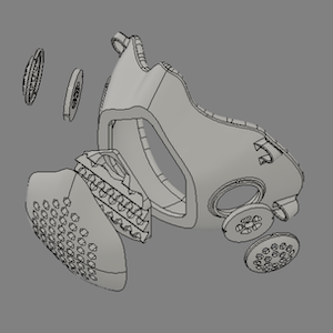 Exploded View
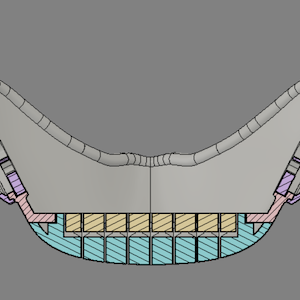 Section Cut – Front Filter
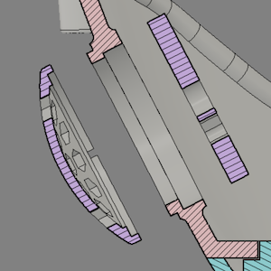 Section Cut – Side Filter
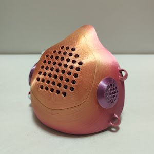 Final Product
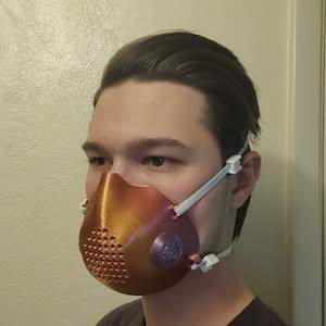 MaxMask in Action
Description
The MaxMask project started as a commission from one of my high school mentors wanting a customizable Covid-19 mask. After many iterations and prototypes, the MaxMask was finally complete and was the ideal 3D printed mask that provided not only customization in color and designs, but also maximum airflow and protection. I used the MaxMask for my communications final pitch for the COM226 course at UAT. I used Fusion 360 for the digital design, my custom KosselMax 3D printer for creation, and anti-microbial PLA for its low cost, variety of colors, and anti-bacterial properties.
Objective Application
The MaxMask fulfills Objective 1 of the DMF degree through the design and fabrication of the mask while meeting human factors such as conforming to the face and creating an air-tight seal. Furthermore, the material choice, form, and function were extremely important for a device people would want to wear and use.
Read about the MaxMask innovation here: MaxMasks – Pandemic Inspires 3D Innovation
2. Demonstrate the ability to evaluate trends in design principles and apply them into the form and function of devices.
 Final Chassis Design
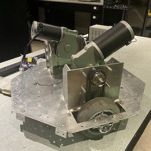 Semester Starting Point
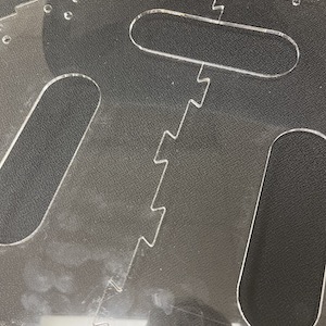 Dovetail Joint for Base Plates
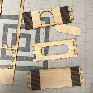 Living Joints for Electronics Box
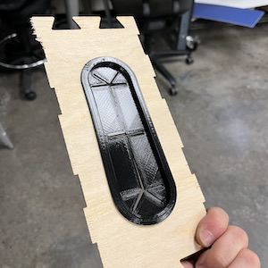 TPU Wire Grommets
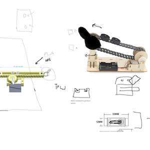 Robotic Arm Brainstorming
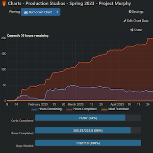 Project Burndown Chart
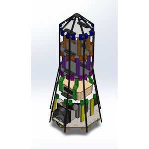 Final Skeletonized Design
Description
For two semesters, I was the Design Lead for the Project Murphy Production Studio Team. The end goal was to develop a tour robot to interact with new and current students in the main building. We started the project with nothing but a bare chassis and by the end of the second semester had a 300+ part assembly. I, along with my team members, integrated modern design practices such as dovetail and living joints, compartmentalized levels throughout the chassis, and a shell/skeleton design technique to follow a seamless design language. I utilized SolidWorks for design, the UAT Maker Space machines for fabrication, and a combination of PLA, TPU, PETG, acrylic, wood, and metal for fabrication materials.
Objective Application
Project Murphy follows Objective 2 of the DMF degree requirements through implementing modern design language methods and techniques, creating functional yet sleek models, and ensuring all parts fit together without collision, non-manufacturable designs, and a bottom-to-top assembly process.
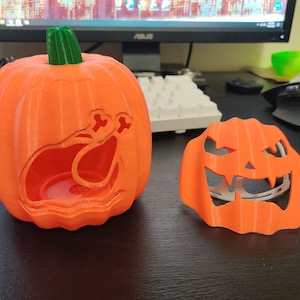 Swap out Faces
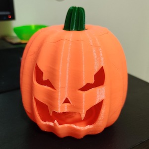 Final Product
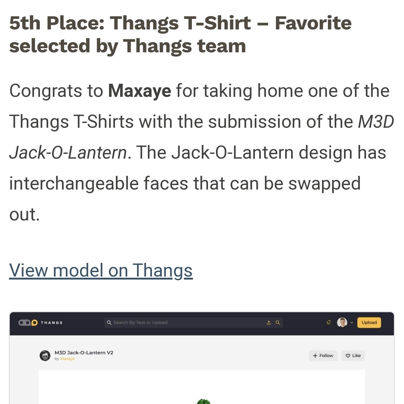 Winning 5th Place for Design
Description
I created the M3D Jack-O-Lantern for a online design contest in 2021. The overall design utilized a jack-o-lantern shape while allowing the front and rear sides to be swapped out for a multitude of different faces. This allowed the end user to be able to print out a single body and choose the exact faces they wanted, which could be swapped out later. I won 5th place in the contest and a T-shirt. I used Fusion 360 for design, my KosselMax 3D printer for fabrication, and PLA for the choice material.
Objective Application
This project applies to Objective 2 of the DMF degree by evaluating Halloween design trends and applying unique and new methods for developing an innovative contest-winning design. The design used industry modeling practices, snap-like features for face attachment, and ended up not only being functional but also fitting the Halloween theme.
3. Demonstrate the ability to evaluate material and build technique options during the creation of products and their prototypes.
 Revision 1
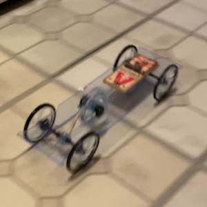 Revision 2
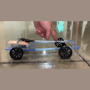 Revision 3
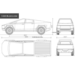 Mock-up for Final Model
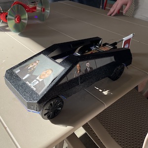 Final Model
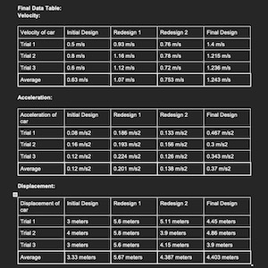 Final Results of Car
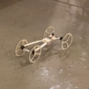
Description
The UAT Mousetrap Car was the final project for the Math & Science in the Real World course. The goal was to develop a mousetrap car that would have the best acceleration, best velocity, or best displacement. In the end, our car wasn’t the best in any of those, but it won the best overall design for its UAT/Cybertruck theme. I utilized Fusion 360 for the design of the car, the laser cutter, vacuum former, and Maker Space 3D printers for fabrication, and a mixture of acrylic, TPU, PLA, and ABS vacuum sheet for the chassis.
Objective Application
The UAT Mousetrap Car falls under Objective 3 of the DMF degree through the evaluation of lightweight and robust materials to ensure the car would move under the power of a mousetrap and utilization of multiple prototypes to finalize the design. Furthermore, specific design techniques were required, such as a gear system, to get the ideal form and function for the car and flag raising system.
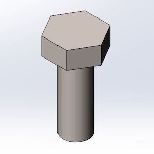 Bolt 3D Model
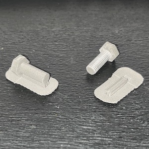 Before and After Post Processing
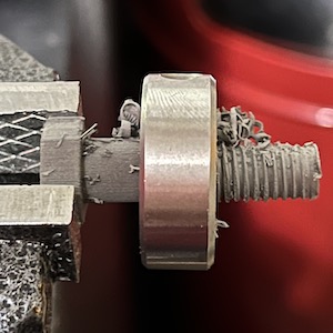 Tapping Threads
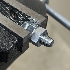 Stainless Steel Bolt Setup
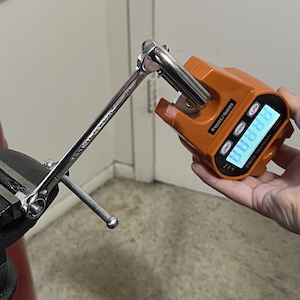 Testing Torque Load
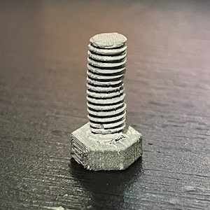 Before Load Test
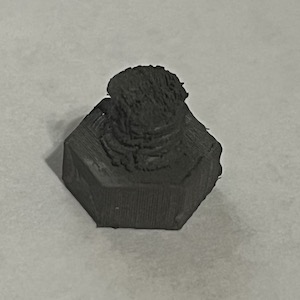 After Load Test
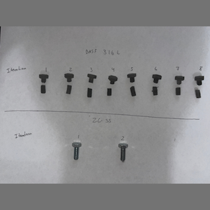 Final Results of Bolts
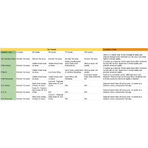 Testing Results
Description
The 3D Printed Fasteners Research Project was my final for the Materials course at UAT. The goal was to conclude whether or not 3D printed fasteners could compare to traditional stainless steel fasteners. In the end, the 3D printed fasteners compared closer to nylon fasteners rather than stainless steel, and I concluded that because the fasteners I made were not sintered, they were much weaker than they should have been. I used SolidWorks for model modification, my KosselMax 3D Printer for fabrication, and BASF 316L Stainless Steel filament and zinc-coated stainless steel bolts for the tested materials.
Objective Application
The 3D Printed Fasteners project relates to Objective 3 of the DMF degree by testing and evaluating different materials, specifically 316L stainless steel filament and zinc-coated stainless steel. The project also applies to the degree objective through the multiple iterations I tested and the data I collected, all of which is present in the documents in my GitHub repository.
4. Demonstrate the ability to evaluate and implement developments within electromechanical, algorithmic, robotic, microprocessor, sensor and other advancing technology areas while making product design decisions.
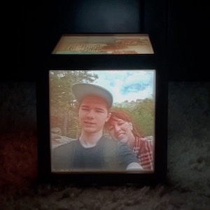 Final Product
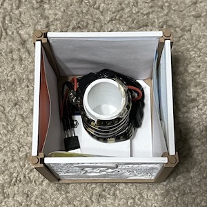 Inside of LithoCube
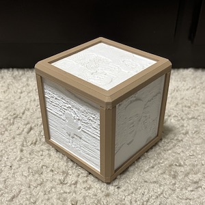 When LithoCube is Off
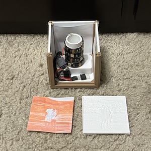 Face Assembly
Description
The LithoCube was a personal project for Mother’s Day of 2022. It consists of a 3D printed casing, with a linear 5V regulator, 9V battery, switch, and LED light strip for the backlight. The process for creating the lithophanes involves having a 1:1 photo and importing that into lithophane generating software such as 3DPRocks. If you want a colored lithophane, you also have to use ItsLitho to get the high saturation backdrop, print that out of paper, and attach to the back of the lithophane. The end product has five total faces that can be swapped out at any time. The model was designed in Fusion 360 then printed on my KosselMax 3D printer out of wood PLA for the frame and white PLA for the lithophanes.
Objective Application
This project applies to Objective 4 of the DMF degree by utilizing electronics and advanced technology to develop a fully-working art piece. The end goal uses electrical components that must integrate with 3D printing technology to deliver a one-of-a-kind piece of art and tech, the LithoCube.
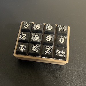 Finished Keyboard
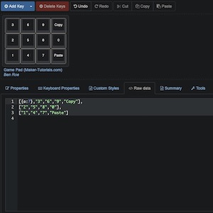 Key Layout
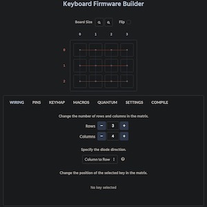 Key Programming
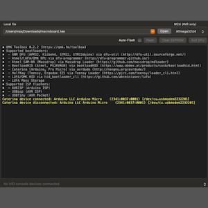 Keyboard Firmware Upload
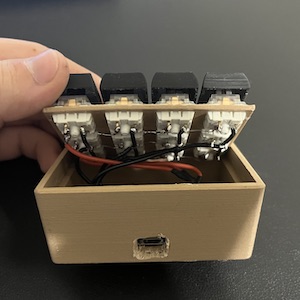 Key Wiring
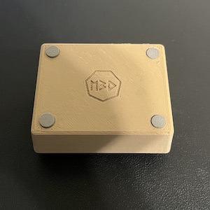 Back of Keyboard
Description
In 2022, I created the M3D MacroBoard to serve as a macro keyboard for my computer. Since I do not have a keyboard that has a number pad, I decided to create my own. This keyboard has all the numbers as well as a copy and paste macro. At any point, the keyboard could easily be reprogrammed to serve any other functions. I utilized KeyboardLayoutEditor to create the key layout, KeyboardFirmwareBuilder to program the keyboard to the specific micro-controller I was using, and QMK Configurator to upload the firmware to the micro-controller. I modeled the keyboard casing in Fusion 360, printed the keyboard out using my Artillery Sidewinder X1, and used wood PLA for a nice look and feel.
Objective Application
This project directly relates to Objective 4 of the DMF degree through the utilization of a micro-processor board, sensors in the form of key switches, and firmware creation and modification to develop an algorithm to interpret key presses as commands. Throughout the creation of the keyboard, multiple product design decisions were made to ensure a simple yet robust keyboard case was fabricated.
5. Demonstrate the ability to work within a maker studio environment to design, build, test and revise products that meet client timeline, design and quality requirements.
 CAD Assembly
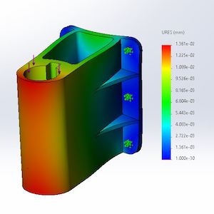 Max. Displacement (0.0136mm)
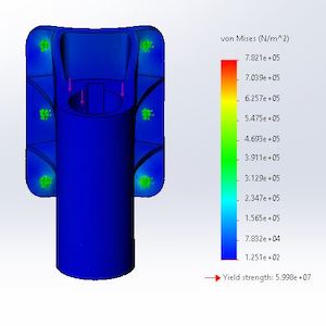 Von Mises Stress (0.0125N/m2)
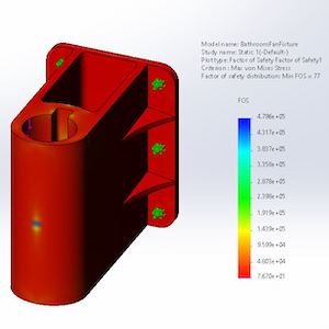 Factor of Safety (77)
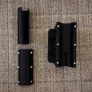 Fabricated Parts
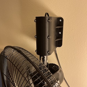 Mounted Fixture
Description
This project was the midterm projects for the Prototyping Tools and Practices course at UAT. The goal was to solve a problem in a clients life through the means of the Engineering Design Process, which included creating a solution selection matrix. After interviewing the client twice, I devised a solution that would mount the client’s existing fan to the wall for better cooling efficiency. I modeled and simulated the design in SolidWorks, fabricated the parts using my Artillery Sidewinder X1 3D printer, and used PLA and TPU for the model materials.
Objective Application
The Fan Fixture projects applies to Objective 5 of the DMF degree by creating a product that not only meets client timelines, but also quality and design requirements. Furthermore, the parts were developed in my own maker environment which heavily involved testing and prototyping. After simulation and model revising, the final fixture was developed and put in place for the client to enjoy.
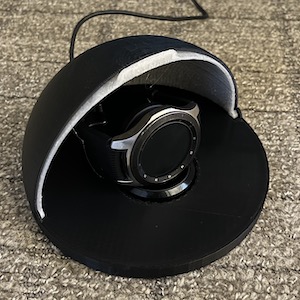 Watch Case with Door Open
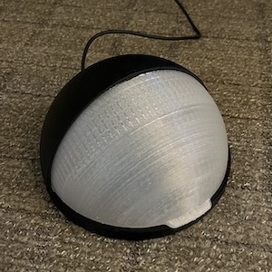 Watch Case with Door Closed
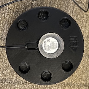 Bottom of Watch Case
Description
The final project for the DBM215 course, Prototyping Tools and Practices, consisted of a small project that involved additive manufacturing and the Engineering Design Process. I interviewed a friend who had an issue keeping their watch on their nightstand as their cat kept knocking it off. After a few interviews and many solutions, I worked with the client to develop a watch case with a door that would allow them to charge their watch without the cat being able to knock it off the nightstand. I used SolidWorks for the model creation, made it on my Artillery Sidewinder X1 printer, and used black and transparent PLA to match their overall room decor.
Objective Application
This project directly applies to Objective 5 of the DMF degree by utilizing the Engineering Design Process to figure out a solution to a clients problem. With that, the clients timeline, design, and overall quality needs were noted and designs were verified with the client before I handed everything over. In the end, an additive solution was the key to my clients issue.
6. Demonstrate proficiency with industry accepted prototyping, modeling, build and maker tools and techniques.
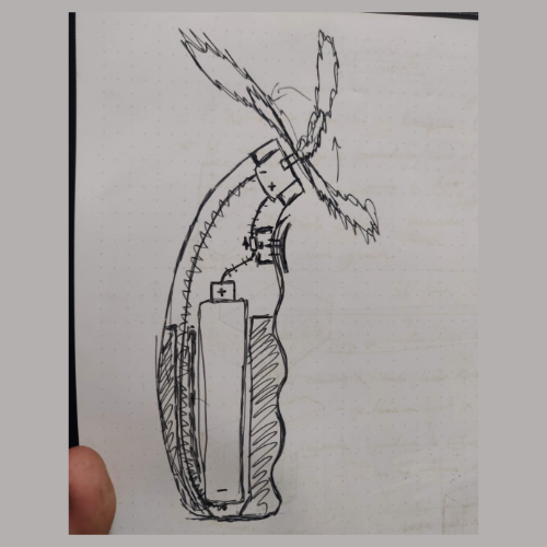 Design Mockup
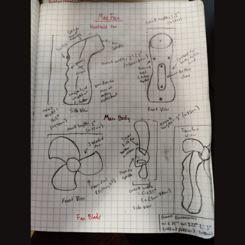 Idea Drafting
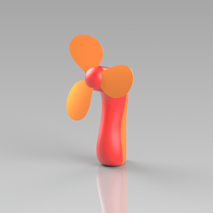 Revision 1
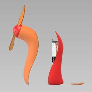 Revision 2
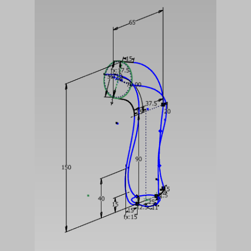 Final Model Sketch Lines
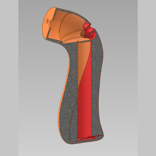 Final Model Section View
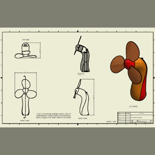 Final Model Drawing
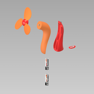 Final Model Exploded View
Description
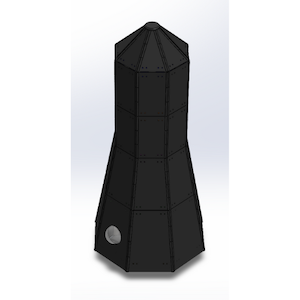
The MaxFan was the final project for my DBM100 3D Build Tools course at the University of Advancing Technology. I made this fan to be able to not only fit in the hand comfortably, but also to be able to stand upright and act as a desk fan. The fan went through many different prototypes before ending on a final revision that included a motor, power switch, battery clips, and batteries to create a fully functional device. I used industry standard software, Autodesk Inventor, to model the components and create the professional drawings that show key dimensions. I did print the final revision in PLA, but I no longer have it anymore as the batteries went dead and it was lost.
Objective Application
The MaxFan project falls under Objective 6 of the DMF degree through the utilization of industry accepted software, Autodesk Inventor. I ensured to use accepted modeling practices such as no part collisions, manufacturable components, and 1:1 scale dimensions to ensure if I wanted to manufacture this, it would be possible. Finally, I created industry parts from scratch such as the battery terminals and fan blade to fully understand how it would be fabricated.
 Opening Software
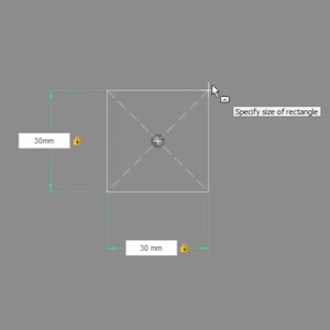 Creating Sketch
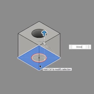 Extruding Sketch
 Final Model
Description
Teaching 3D Build was a required assignment for the 3D Build Tools course at UAT. This assignment required you to create an educational teaching video about 3D CAD software after spending a semester using a modeling software and understanding it. I chose to not use the software that was taught in the course, Autodesk Inventor, and instead chose to teach Autodesk Fusion 360 as I was far more versed in the application. In the end, I demonstrate from start to finish how to model a 30mm cube with a 15mm cylinder cut out of the center.
Objective Application
Teaching 3D Build applies to Objective 6 of the DMF degree through demonstrating complete proficiency of the industry accepted modeling software, Fusion 360. It further demonstrates how to prototype, model, and build within the 3D CAD software and would be a perfect instructional video for someone who has never touched the software before. It explains accepted techniques and how to create your own 30mm cube.
Robotics & Embedded Systems Objectives
1. Design and complete robotic and embedded systems solutions that apply to real-world situations and challenges.
 Final Product
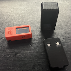 Fabricated Components
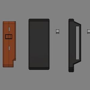 Exploded View
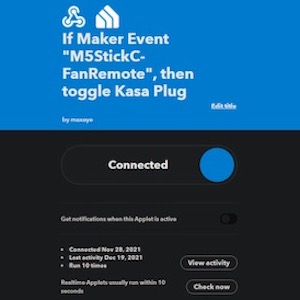 FireBase Connection
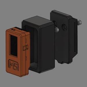
Description
In this project, I made an M5StickC powered remote to be able to turn off and turn on my fan without having to get up or from other rooms than where the fan is. The planning behind this project was to compare its feasibility, price, and user experience to my $100 fan that has an IR remote.
Objective Application
This IoT remote applies to Objective 1 of the RES degree through being able to assist in real life situations through the power of internet connected devices, while allowing attachment to the user through magnets. Furthermore, it allows any basic fan to be able to be turned into a smart fan.
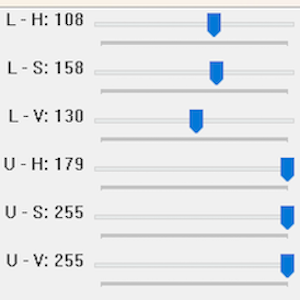 HSV Settings
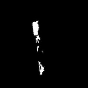 Masked Image
 Coordinate Detection
Description
This project was a stepping stone for creating a soccer ball playing robot for the Robot Competition course. As the lead for object detection, I used OpenCV along with Python, a Raspberry Pi, and camera to detect colors and find their positions on screen so that the robot could determine where to move.
Objective Application
This robotic application applies to Objective 1 of the RES degree by using technology to allow a robot system to detect objects and color in the real world. This could also be adapted for use with the color blind or fully blind to detect objects or colors where needed in real life.
2. Implement a simple microprocessor using digital logic design.
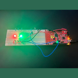
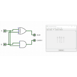 Logisim Circuit
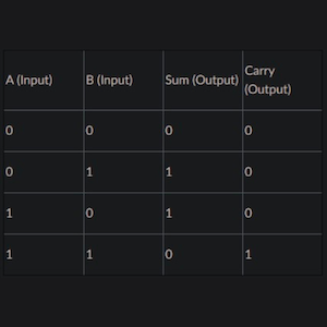 Truth Table
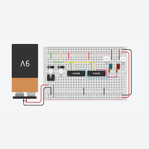 Final Circuit
Description
For the RBT131 course, I developed a half adder circuit in Logisim and TinkerCAD. This basic digital circuit adds two binary digits together, here in the form of switches. It has two inputs (A and B) and two outputs (Sum and Carry). The circuit performs addition without a carry from a previous operation.
Objective Application
This project directly applies to Objective 2 of the RES degree by creating an addition device through basic logic gates. This system can be further built upon, but in its basic state it is able to add two digits together without code or any special programming.
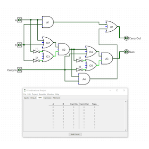 Logisim Circuit
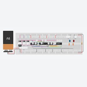 Final Circuit
Description
The final project for the RBT131 course involved developing a full adder circuit in Logisim and TinkerCAD. A full adder circuit is more advanced using three binary digits rather than two. It has three inputs (A, B, and Carry-in) and two outputs (Sum and Carry-out). The circuit takes the carry from a previous addition, allowing it to add multiple binary numbers together.
Objective Application
This project applies to Objective 2 of the RES degree by allowing basic logic gates to do simple addition. In its current form, it is able to count in binary all through AND, OR, and NOT gates. With four of these put together, we could create a 4-bit adder.
3. Demonstrate embedded system design skills, including, but not limited to, microcontroller selection, schematic design, printed circuit board layout, design for electromagnetic capability and design for manufacturing.
 Concept Design
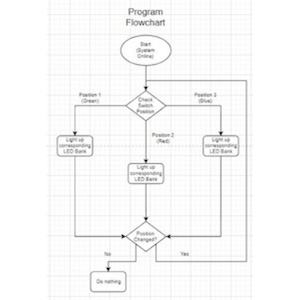 Program Flowchart
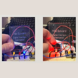 Prototype One
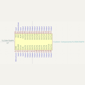 TLC5947 Schematic
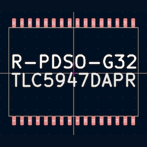 TLC5947 Package
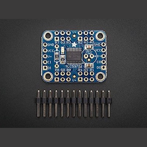 TLC5947 Board
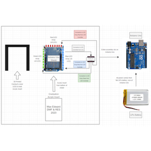
Description
The final project for the PCB Build course was based around developing a badge for the spring 2023 graduation. The circuit is run off a 3.7v LiPo battery and an Arduino Uno. On top of the Uno sits a shield that has 24 LEDs. For inputs to these LEDs, a TLC5947 LED controller SOC is used. The badge casing is 3D printed to cover up the LEDs and direct light. Furthermore, the casing will include a slot to hold an acrylic insert that can read any kind of information.
Objective Application
The project applies to Objective 3 of the RES degree through the design of an embedded system that includes microcontroller selection by exploring the TLC5947 SOC, board layout through creating a custom Arduino Uno Shield, and design for manufacturing by developing a process for creating the badges.
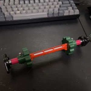
 Team Work
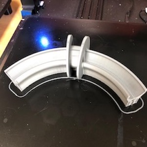 Ring Fabrication
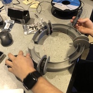 Ring Assembly
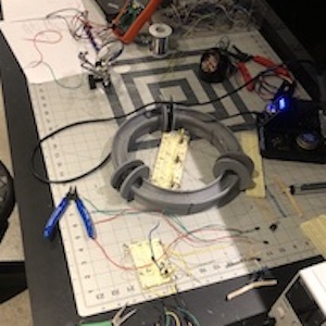 Testing Coils
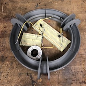 Final Product
Description
This was a personal project completed by Michael B., David D. P., and myself. The goal of this project was to develop a desk decoration for my workplace. The device uses 1″ metal ball bearings, IRFZ44 MOSFETs as high speed switching transistors, 5mm IR transmitters and receivers to detect when the ball bearing is in position, and a 3D printed housing. The end result was a small ring that could sit on your desk and move while you were working.
Objective Application
This project applies to Objective 3 of the RES degree through choosing the correct power controllers, designing an electromagnetic system, and design for manufacturability through 3D printed components. Furthermore, consideration had to be done for the components chosen as there was no microcontroller or programming involved, making it an overall more simple device.
4. Demonstrate the ability to evaluate and implement developments within electromechanical, algorithmic, robotic, microprocessor, sensor and other advancing technology areas while making product design decisions.
 Conveyor Gear Assembly
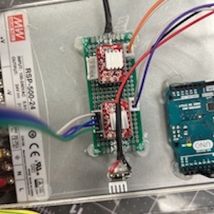 A4988 Driver Protoboard
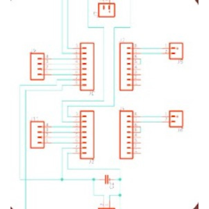 A4988 Driver Schematic
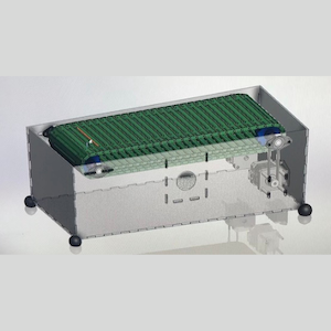 Computer Design
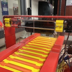 Conveyor Belt Topside
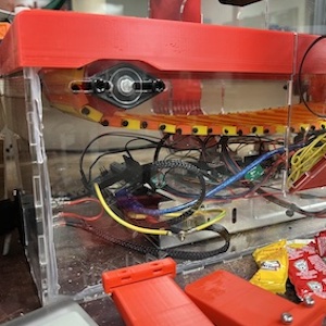 Conveyor Belt Underside
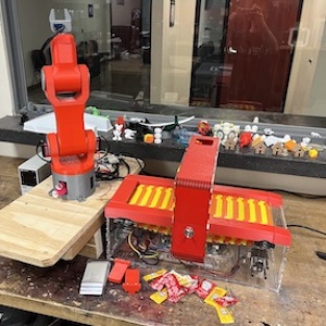 Final Design
Description
The hotdog serving machine was the final project for the RBT479 Mechatronics course. This system allows for a hotdog to be chosen, the robot arm then places it on the conveyor belt, the conveyor belt moves to the condiment position and applies the condiment, then it moves the hotdog to the end where it is served to the user. Ideally, the real thing would be fully enclosed and automatic to where the user just has to input what condiment they want, if any.
Objective Application
The project applies to Objective 4 of the RES degree by implementing actuators, microprocessor, and drivers and switches to be able to serve a user with a hotdog. Furthermore, a custom A4988 stepper motor driver board was made. Additionally, the system was designed with form and function in mind with many 3D printed items were incorporated.
 Before Modification
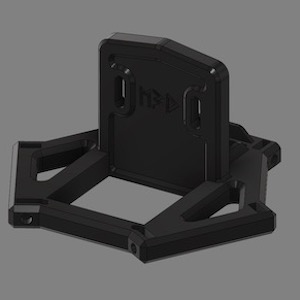 Gantry Design
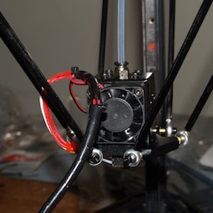
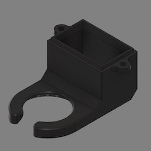 New Part Cooling Duct
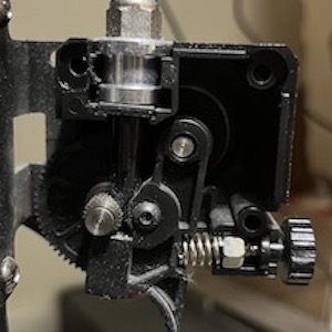 Extruder Assembly
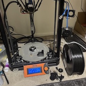 Hardware Modification
 Marlin Firmware
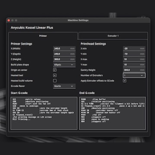 Slicer Changes
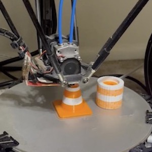 Dual Extrusion Printing
Description
This was a personal project to turn my single extrusion delta 3D printer into a dual extrusion machine. I redesigned the gantry system, added a new hotend system, reprogrammed the PID tuning and added in variables for another extruder in the firmware. I also routed a new motor and driver onto the main board. After testing the new system, it works very well for both dual-color and dual-material applications.
Objective Application
This directly applies to Objective 4 of the RES degree by modifying machine algorithms and hardware with design in mind. I incorporated a second motor system, new hotend, and made slicer software changes to handle a second extrusion path.
5. Design and analyze real-time embedded systems, including advanced digital logic design, signal processing, and high-speed digital systems.
 Initial Concept
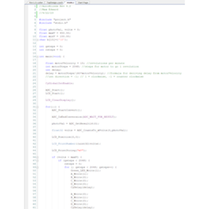 ARM Programming
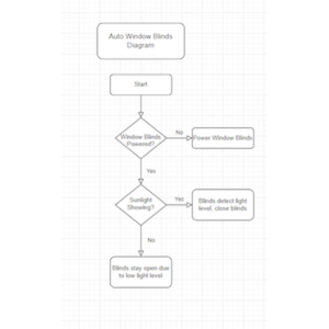 Program Flowchart
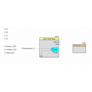 Object Setup
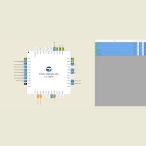 Pin Designation
 Build Successful
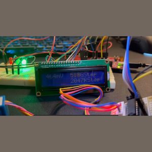 LCD Readout
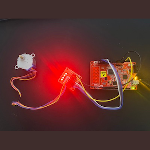 Final Product
Description
The final project for the SPT323 Arm Programming course was an automated system for my blinds in my room. I was constantly having to raise and lower them to keep the sun out and my room from getting hot. I came up with a device that read light values through the window, and would open or close the blinds depending if it was light or dark outside.
Objective Application
This project applies to Objective 5 of the RES degree by implementing real-time analysis of light levels coming in through the window, processing that data with a high-speed STM32 processor, utilizing ADCs, and actuating a stepper motor to open or close the blinds accurately.
 Batter Testing
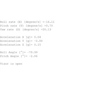 Real-time Data Analy
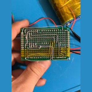 Circuit Board Wirin
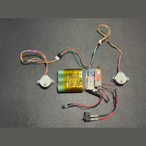 Completed Circuit
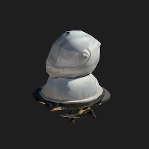 3D Scanning Helmet
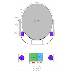 Component Layout
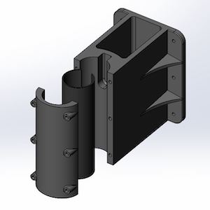
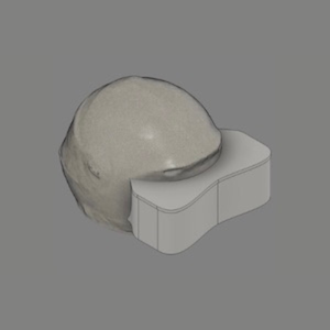 Casing Model
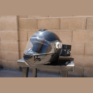 Final Product
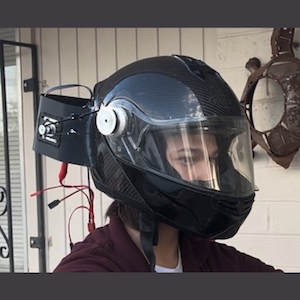 AutoVisor In Action
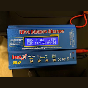
Description
My senior innovation project, the AutoVisor, was a device that would attach to a motorcycle helmet and allow for the automatic actuation of the visor without physical interaction from the user. It utilized an accelerometer, gyroscope, and magnetometer sensor for data analysis, Arduino Pro Micro for processing, Dual Nema 17 stepper motors for actuation, and 18650 batteries for power.
Objective Application
This project directly applies to Objective 5 of the RES degree through analyzing in real time head tilt and acceleration, high-speed processing the information, and commanding the motors depending on the data. Furthermore, care was taken to develop a digital logic circuit to operate on 5v and 12v rails both powered by the 18650 Li-Ion power system.
6. Implement and evaluate algorithms and methods enabling autonomy in a mobile robot.
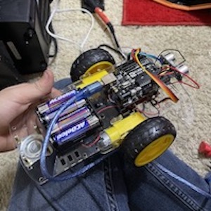 Final Product
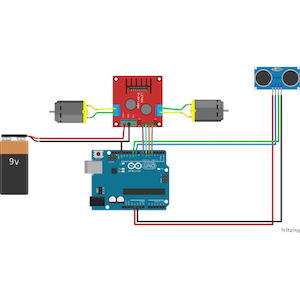 Wiring Diagram
 Robot Program
Description
The RBT173 course explored the idea of using an ultrasonic sensor to control a vehicle autonomously. By getting distance data from the sensor on the front of the vehicle, the smart car would know how far it is from a object and be able to turn around and move away. This system was powered with four AA batteries and processing was done by an Arduino Uno.
Objective Application
This project applies to Objective 6 of the RES degree by utilizing an ultrasonic sensor for autonomous control of the robotic car; no human interaction is needed for the car to run. Furthermore, it implements specific algorithms to be able to know how far it is from an object and how far to turn to start in a new direction.
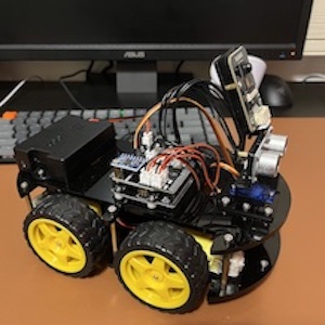 Final Product
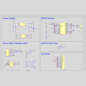 Circuit Diagram
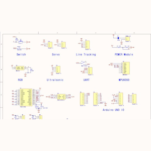 Component Diagram
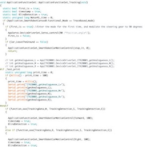 Robot Program
Description
In the RBT347 Robot Navigation course, our end goal was to understand how a multi-functional autonomous mobile robot operates. We explored using the robot in wireless remote mode, as well as the included ultrasonic and follow modes. However, we specifically studied the line following mode and tried to better understand how this could be used in the real world.
Objective Application
The robot car project applies to Objective 6 of the RES degree by being able to follow a line autonomously and without human intervention. Furthermore, this robot also has the capability to operate in an obstacle avoidance mode and subject follow mode, further enabling autonomy.